4.1 Display Interface Introduction
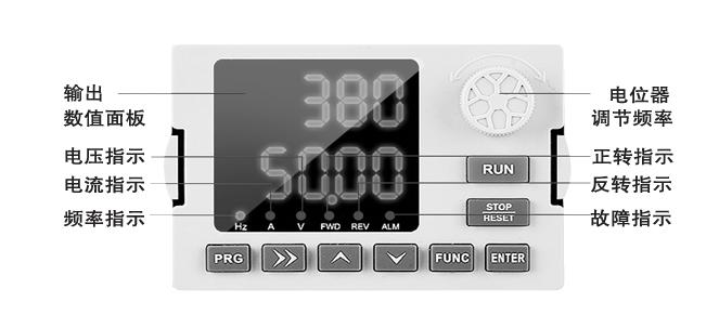
The operational panel allows for functional parameter modification of the variable frequency drive (VFD), monitoring its operational status, and performing operations such as start and stop. Its appearance and functional areas are depicted in the following figure:

Functional Indicators and Buttons on the Operational Panel of C Series Variable Frequency Drives
| Symbol | Name | Function Description |
|---|---|---|
| PRG | Program Key | Enter or exit menu, modify parameters |
| ENTER | Enter Key | Select parameter modification, shift, and display content |
| 🔼 | Increment Key | Increment data or function code |
| 🔽 | Decrement Key | Decrement data or function code |
| ▶️ | Shift Key | Switch selection based on function |
| RUN | Run Key | Enter menu, confirm parameter settings |
| STOP/RESET | Stop/Reset Key | Run operations in keyboard operation mode |
| FUNC | Multi-function Shortcut Key | Jogging |
| REV | Indicator Light | Inverter reverse indicator light, lit when in reverse operation status |
| FWD | Indicator Light | Inverter forward indicator light, lit when in forward operation status |
| ALM | Indicator Light | Inverter fault indicator light, lit when in fault status |
| Hz | Indicator Light | Frequency unit |
| A | Indicator Light | Current unit |
| V | Indicator Light | Voltage unit |

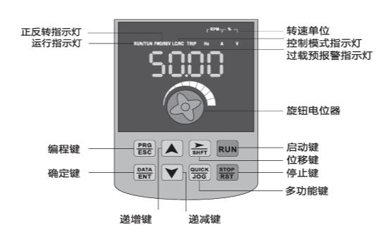
Functional Indicators and Buttons on the Operational Panel of H Series Variable Frequency Drives
| Name | Function Description |
|---|---|
| Unit Indicator Lights | Hz: Frequency unit; A: Current unit; V: Voltage unit;RMP(Hz+A): Speed unit; %(A+V): Percentage |
| Status Indicator Lights | RUN: On/Running; Off/Stopped;FWD/REV: On/Forward; Off/Reverse; Flashing/Transitioning between forward and reverse;TUNE/TC: Slow Flashing/Tuning mode; Fast Flashing/Communication mode; Slow flash about once per second; Fast flash about twice per second;LOCAL/REMOTE: On/Terminal control; Flashing/Communication control; Off/Keyboard control. |
| PRG (Program Key) | Enter or exit primary menu |
| ENTER (Enter Key) | Navigate through menu screens, confirm parameter settings |
| 🔼 (Increment Key) | Increment data or function code |
| 🔽 (Decrement Key) | Decrement data or function code |
| ▶️ (Shift Key) | In stop display and run display modes, cyclically select displayed parameters; when modifying parameters, select the parameter modification bit. |
| RUN (Run Key) | Used for running operations in keyboard operation mode. |
| STOP/RESET (Stop/Reset Key) | In run state, press to stop running operations; in fault alarm state, use to reset operations, characteristics of this key are constrained by function code F7.02. |
| MF.K (Multi-function Shortcut Key) | Function selection switch based on F7.01. |
| Knob (Pulse Potentiometer) | Can be used as frequency setting source. When set as frequency source for the inverter, clockwise rotation increases the setting, counterclockwise rotation decreases the setting. |
Explanation of Viewing and Modifying Function Codes on the Variable Frequency Drive
The operational panel of the variable frequency drive uses a three-level menu structure for parameter settings and other operations. The three levels of menus are: function parameter level (primary menu) → function code (secondary menu) → function code setting value (tertiary menu). The operation process is depicted in the following figure:

Note: When operating in the tertiary menu, pressing the PRG (programming) key or ENTER (confirm) key will return to the secondary menu. The difference between the two is: pressing the ENTER (confirm) key will save the parameter settings and return to the secondary menu, automatically moving to the next function code; pressing the PRG (programming) key will directly return to the secondary menu without storing parameters and return to the current function code.
Example: Changing function code P3-02 from 10.00Hz to 15.00Hz. (Bold indicates blinking bit)

In the tertiary menu state, if parameters do not have a blinking bit, it indicates that the function code cannot be modified. Possible reasons include:
- The function code is a non-modifiable parameter. Such as actual detection parameters, running record parameters.
- The function code cannot be modified in the running state and needs to be stopped before modification.
Explore these documents to learn more.